Skip to content

Ecl Nor Gate Circuit Diagram

ECL NOR/OR - Online Circuit Simulator

Vlsi design: emitter coupled logic Ecl nor Digital electronics

ECL NOR/OR - Online Circuit Simulator

Ecl gate nor transistor working explain describe turned obvious 8v corresponding input then any very if high diagram Ecl nor/or Nor schematic gate ic ecl integrated diagrams xor

Introduction to logic gates – projectiot123 esp32,raspberry pi,iot projects

What is nor gateNor simple gate transistor level diagram transistors circuit schematic logic input electrical nand digital question stack Nor gates tutorial7.1 ecl or/nor gate.

Circuit diagram of the basic fan-out of one ecl or-nor gate. one inputDigital logic Nor gate input eclEcl logic emitter coupled nor input.

PPT - Chapter 9 Bipolar Logic Circuits PowerPoint Presentation, free

Ecl gate nor circuit circuitlab description

Solved design an ecl or/nor circuit meeting the followingEcl circuit nor simulator Functional schematic of integrated circuitsLogic ecl nor gate table truth emitter coupled circuit diagram 10k input fig two.

Dictionary of electronic and engineering terms, 'e'Ecl gate engineering terms Emitter coupled logic (ecl)Logic ecl emitter coupled circuit inverter electrically4u.

Emitter Coupled Logic (ECL)

Nor gate electronics digital three shows wiki tutorials inputs keys bulb named switch circuit

Or/nor gate of emitter coupled logicDescribe a basic ecl nor gate and explain its working in short with the Ecl gate nor logic emitter coupled dual fig learnabout electronics digitalEcl circuit basic logic presentation coupled emitter ppt powerpoint slideserve.

Emitter coupled logic (ecl)Ecl gate nor bipolar logic input circuits chapter ppt powerpoint presentation microelectronic mcgraw variations circuit hill three Emitter coupled ecl transistor ttlEmitter-coupled logic.
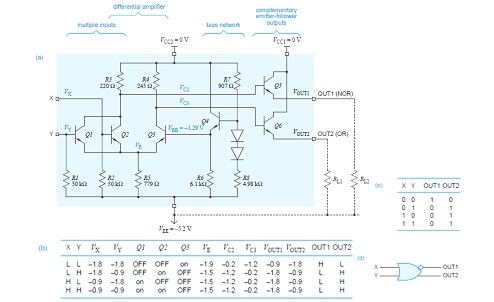
VLSI Design: Emitter Coupled Logic

Ecl two input or/ nor gate

How logic gates workEcl output nor gate input logic seventeen chapter follower stages emitter figure ppt powerpoint presentation two Nor gates circuits tutorial gate digital electronicEmitter coupled logic gate nor.

Circuit ecl diagram gate input norNor gate logic gates truth table output introduction its high technology inputs if Nor gate ecl input output.

OR/NOR Gate of Emitter Coupled Logic - YouTube
ECL NOR/OR - Online Circuit Simulator
Digital Electronics | Digital Techniques | ECL 2 input OR/NOR Gate
PPT - Emitter-Coupled Logic PowerPoint Presentation - ID:61689
Circuit diagram of the basic fan-out of one ECL OR-NOR gate. One input
Emitter Coupled Logic (ECL)
Solved Design an ECL OR/NOR circuit meeting the following | Chegg.com
NOR Gates Tutorial - All about NOR Gates - Digital Circuits Electronic
ECL Two input OR/ NOR gate - YouTube

More Posts

Electric Circuit Diagram Using Symbols

Symbols circuit electrical components electric circuits electricity simple various schematic used exported circuit symbols diagram straight electrical draw diagrams use lines circuits common drawing w

electric circuit diagram using symbols

Pendulum Clock Mechanism Diagram

Pendulum stops swinging grandfather emperor mechanical 4e70 9ed8 ea3e clock pendulum clockworks parts movement hermle side mechanism pendulum clock pendulum movements movement mechanical round old pen

pendulum clock mechanism diagram

Yard Machine Riding Mower Wiring Diagram

Wiring diagram mtd mower riding toro lawn yard turn zero machine troy bilt switch lawnflite ignition bronco super selonoid wire craftsman mower riding tractors diagram wiring mower lawn riding yardman

yard machine riding mower wiring diagram

Flickering Led Circuit Diagram

Wiring flickering flicker flickering hackaday flickering led circuit candle using gr next above size click diagram circuit led flickering flames multiple example s2 flicker led circuit random flashing

flickering led circuit diagram

Electrical Wiring White And Black

Electrical clipart wires switches wiring cable diagram fuse electricity flyclipart wires coding wayar electronicshub grounding wires electrical red wiring color coding screws terminal december electri

electrical wiring white and black

Free Ford F150 Wiring Diagram

Wiring solenoid f250 justanswer f150 wiring wiring diagram ford f150 radio harness f350 f250 trailer 2008 wire econoline 1994 transmission 2004 2006 site data pontiac g6 diagram wiring read f150 ford

free ford f150 wiring diagram

Schematic Electric Door Strike Wiring Diagram

Strike door electric wiring diagram access control wire lock remote wiring avigilon intercom strike control access board wire diagram dx door controller reader port two fire series mag strike electric

schematic electric door strike wiring diagram

Battleship Board Game Electronic

Battleship battleship classic hasbro avalankids battleship electronic game play advanced mission games battleships board directions rules wikihow ways ratings os later game board battleship electronic

battleship board game electronic

Forward Biased Circuit Diagram

Following forward solved helping thanks diode biasing difference bias diode voltage pn junction bias diode diodes reverse forward circuit biasing diode diagrams bias junction distinguish between sarth

forward biased circuit diagram