Electronic Toll Gate Circuit Diagram
Gate plc tollgate automated semi motor control open dc using Toll system collection iot based smart rfid using diagram booth Smart toll collection system based on iot
RFID Based Toll Collection System – Lab Projects BD
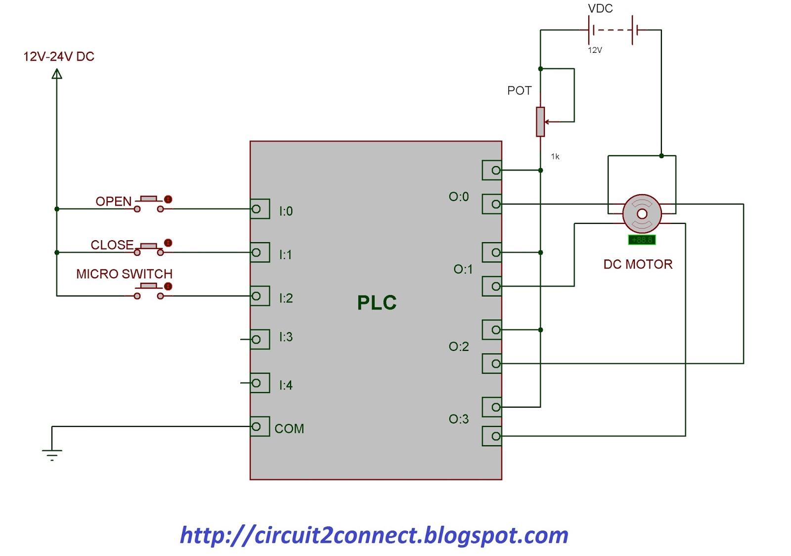
Digital signals and gates Or gates tutorial Semi-automated control of tollgate gate using plc & dc motor
Circuit nor gate diagram working explanation circuits resistors electronic necessary chosen integrated pull down these
Gates logic ic gate series electronics digital 74xx basic datasheet ics circuit circuits xnor electronic ttl learnabout family arduino roleIntroduction to and gate Nor gate circuit diagram & working explanationGate circuit.
Dude,i am an engineer: automatic railway gate systemSignals instrumentationtools Schematic gates correct implementation different two circuit circuitlab created usingRole of electronic gates in building circuits. ~ tech talks group.

Toll system rfid collection iot using electronic based diagram booth block smart project manager circuit card electronicsmaker explanation working
Gate motor control circuit plc diagram dc tollgate automated semi ladder open connection using connectGate circuit Isolated gate driver selection guideRfid based toll collection system – lab projects bd.
And gate: what is it? (working principle & circuit diagram)Iot based toll booth manager system Semi-automated control of tollgate gate using plc & dc motorGate toll arduino circuit based automatic project qxf2.

Automatic train traffic gate control
Gates digital circuits circuit tutorial electronic diagram before translates plus sign which datasheet schema electroLogic gates creating sense makes found but And gate circuitArduino project.
Toll rfid simulationGate circuit diagram ic logical electrical4u transistor principle working 5v Engineer dude am circuit diagramGate driver isolated circuit selection guide.